Product Description
|
| Product Information | Resources |
|
|
| Specifications |
| Product Attribute | Attribute Value |
| Function | Operating configuration independently applied to each channel |
| Control Voltage | 102-132V AC & 10-125V DC |
| Number of Channels | 4 |
| Enclosure Style | 60mm |
| Operation | 2 Poistion Dip Switch that selects a single configuration for all channels |
| Load (Burden) | 5VA Maximum |
| Input Switch Open Circuit Voltage | 10V DC |
| Output Contacts | SPST-NO (Form A) 3A Resistive @ 125V AC @60°C & 30V DC Resistive, Pilot Duty Rating D300 SPST-NO (Form A) 5A Resistive @ 125V AC @40°C & 30V DC Resistive, Pilot Duty Rating D300 |
| Electrical Life | 50,000 Closures @ Full Load AC |
| Mechanical | 5 Million Closures @ No Load |
| Response Times | Standard (DIP Switch set to “0S”): < 50ms Delay (DIP Switch set to “2S”): Fixed 2 Seconds |
| Operating Temperature | -28o to + 60o C (-18o F to +140o F) |
| Storage Temperature | -55o to +85o C (-67o to 185o F) |
| Insulation Voltage | 1500 V AC between coil & contacts 750 V AC between open contacts 1500 V AC between contacts of different output channels 1500 V AC between hazardous and safe circuits |
| Wire Sizes | One #14-24 AWG Conductor or Two #16 or 18 AWG Conductors |
| Mounting | Mounts on 35mm DIN-rail or panel-mounted with two #8 screws when DIN-rail clips are fully extended from under the enclosure. |
| Series Features |
| ISD Series 60 MM INTRINSICALLY SAFE BARRIER RELAYS |
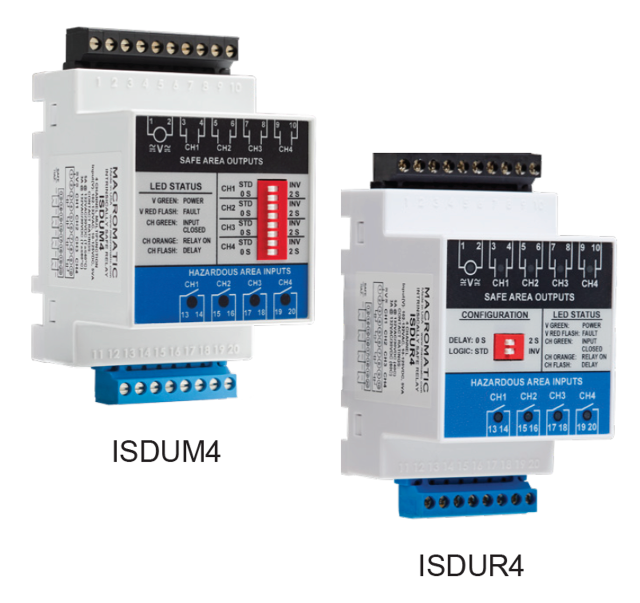
| Series Description: The ISD Series of Intrinsically Safe Barrier Relays provide a safe and reliable method to control up to four loads (motor starters, relays, etc.) with up to four input devices (switches, sensors, etc.) located in a hazardous area. The ISD Series relays utilize a compact 60mm wide enclosure that can be both mounted on 35mm DIN rail or panel-mounted with two screws. Terminals for the input devices from the hazardous area are on the bottom of the unit for easy access in the enclosure to incoming field wiring from the hazardous area. Pluggable terminal blocks on both the input and output sides allow for easy initial wiring of the unit as well as replacement without having to remove any wires. Each input has two terminals supporting direct connection of 2-wire input devices eliminating the need to mount a separate terminal block. Each output relay is isolated with two wiring terminals providing a true normally-open contact. This allows the output contacts to be used in complex control circuits and allows for each output to switch different voltages with respect to other outputs and the input voltage. A universal input voltage of 102-132V AC & 10-125V DC covers a variety of applications with one device. |
| Operation: Each ISD Series product consists of 4 intrinsically safe inputs and four corresponding normally-open relay outputs. With input voltage applied, the V LED will be ON (GREEN) to indicate power is applied. When the input device is closed, the input LED is ON (GREEN). When the output relay is closed, the output LED is ON (ORANGE). The ISD series offers four user-selectable configurations built in. ISDUR4 has a two-position DIP-switch that selects a single configuration for all channels. ISDUM4 has an eight-position DIP-switch that selects a configuration for each channel, independently. Configurations Standard Logic (DIP Switch set to “STD”): When the input device is closed, the corresponding output contact is closed. When the input device is open, the corresponding output contact is open. Inverse Logic (DIP Switch set to “INV”): When the input device is open, the corresponding output contact is closed. When the input device is closed, the corresponding output contact is open. No Time Delay (DIP Switch set to “0 S”): The output contact changes state immediately in response to a change in input device state. 2 Second Delay (DIP Switch set to “2 S”): The output contact will delay 2 seconds before changing state in response to a change in input device state. |
|


 RoHS Compliant