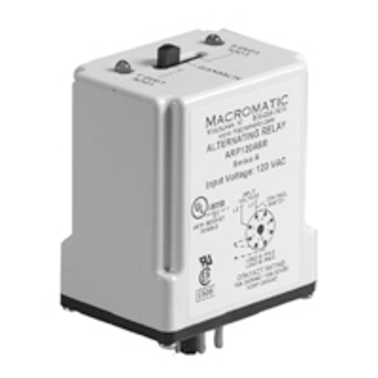
Series Description: Alternating Relays are used in applications where the optimization of load usage is required by equalizing the run time of two loads. This alternating action is initiated by a control switch, such as a float switch, manual switch, timing relay, pressure switch, or other isolated contact. Each time the initiating switch is opened, the output relay contacts will change state, thus alternating the two loads. Two LEDs indicate which load is the next to energize.
These Alternating Relays are available in either SPDT or DPDT output configurations and typically are used to control two loads, with only one on at a time. For products used when additional capacity is required (ability to turn both loads on at the same time), see Alternating Relays with DPDT Cross-Wired output configurations.
Each version is available with an optional three-position selector switch. This allows the unit to alternate the two loads as normal or select one or the other load to be the only one energized when the control switch closes. A load that has fewer hours than the other load could be used more often to eventually balance the run time of both loads. The selector switch has a low-profile to prevent any accidental changes in status. |


 RoHS Compliant